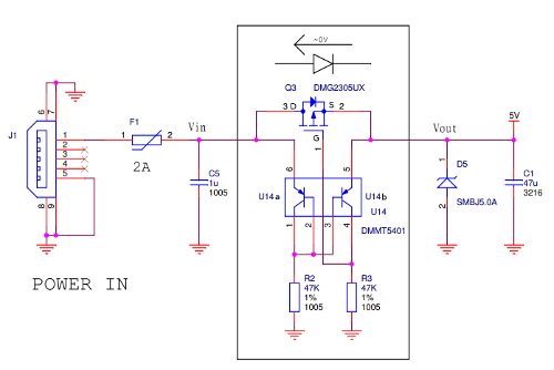
I just bought the newly relased Raspberry Pi (RPI) model B+. In comparing the schematic with the older model B, I noticed they have updated the power protection circuit.
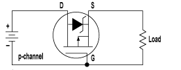
The circuit functionality is mostly obvious. There is polyswitch F1, a self-resetting fuse which protects the RPI from overcurrent condition. There is the Transient Voltage Suppressor (TVS) diode D5 which protects the RPI against static discharge and possibly overvoltage condition. However, the function of mosfet Q3 together with the matched PNP transistors U14 is not so obvious. A mosfet is usually used as a reverse polarity protection, but such protection is not needed for the RPI because of the polarized USB connector used.

“RPI B+ Power Protection Circuit”

“Reverse polarity protection with mosfet”
I wasn’t able to work out the PNP pair functionality by searching the Internet. Adafruit also noticed this transistor pair but did not offer useful explanation.
It turns out that the matched PNP transistors are used as voltage comparator. When Vin > Vout, the PNPs are biased in such a way that the mosfet is switched on. When Vin < Vout, the mosfet is switched off. In another word, the circuit acts as a diode letting current to flow only in the forward direction. The advantage of this "diode" over silicon or even schottky diode is the much lower voltage drop.
This diode functionality is important because when the RPI is connected to a computer USB port, the RPI must never source current upstream into VBus. Without this PNP circuit, if there is voltage present on Vout, the mosfet will be turned on. Voltage on Vout will be present if the RPI is powered through the GPIO expansion port. If this applied voltage happens to be higher than VBus, then current will flow into VBus, potentially damaging the computer.
The way the circuit works is this: if Vin=Vout, lets say 5.0V, the PNP transistors are biased in a current mirror configuration. Vb of transistors U14 will be 5-0.6=4.4V, the mirroring configuration means that Vg will also be at 4.4V. Vgs is 4.4-5.0=-0.6V. The mosfet will be in the off state (almost turned on).
If Vout is slightly lower than Vin, lets say 4.9V, U14a will still be biased as before, so Vb is still 4.4. Vbe of U14b will now be 4.4-4.9=-0.5, U14b will be off and Vg will be 0V since no current flows through R3. Vgs will be 0-4.9 = -4.9V, and the mosfet will be fully switched on.
If Vout is slightly higher that Vin, lets say 5.1V. U14b will be turned on via the biasing resistor R2. Transistor U14b will be in saturation mode and Vg will be 0.2 V lower than Vout, Vgs = -0.2, and the mosfet will be off.
Conclusion
The protection circuit in the RPI model B+ functions as an ideal power diode.
Hi!, your explanation is great, thanks a lot for the analysis.
I’ve replicated the circuit that Raspberry suggests, powering Raspberry Pi only through GPIO, and I get an intermitent cut. Could it be because they’re using different resistor values for each transistor?, anyway I’m going to use two 47k Resistor and see what happens.
Thanks a lot!
Diego
Hi,
Thanks for great explanation. I think this protection is necessary if you power the Pi from USB hub. This protects the power supply or laptop, that is connected to USB micro.
That is looks so complicated