M5Stack review. An Espressif ESP32 development kit.

I received the M5Stack Core development kit last week. I’m quite excited about this, and would like to share my thoughts on it.

The kit is based on Espressif ESP32 microcontroller. It is a System-on-Chip (SOC) microcontroller that is becoming extremely popular. There are great reasons for this popularity. The chip includes Wi-Fi and Bluetooth connectivity, connectivity that is very relevant for modern projects. Another important reason for the popularity is the availabiltity of free development tools. GCC based compilers, Arduino, Micro Python, etc are all available. However, the most important reason for the popularity is the low cost. Chips, modules, and development boards are readily available at low cost.

M5Stack is a great awesome development platform. It enables the development of aestheticly-pleasing prototype with little effort. It may even be ideal for low-volume production. The modular stackable expansion system is quite ingenious. Custom circuit is “stacked” at the bottom of the kit. The circuit can then be enclosed with relative ease. The difficult task of enclosing the user interface elements (screen, buttons, etc) have been done for you.

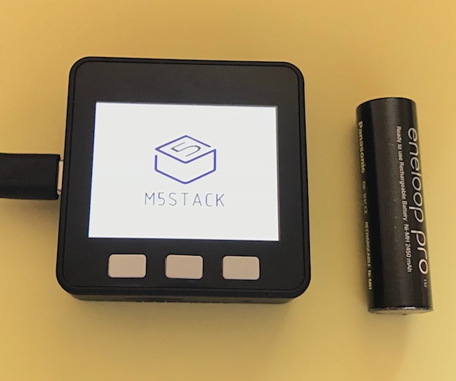
M5Stack next to AA battery for size reference

The core module is equiped with well-chosen user interface peripherals. The set of peripheral is good for most projects. They include:

  • 2″ 320×240 LCD screen. (quite sharp, mainly due to the small size)
  • 3 buttons
  • a speaker, and
  • on/off – reset push button.

The setting up of the Arduino developemnt environment is well documented and is straight forward. Software libraries for accessing the LCD, speaker and buttons are provided. This is a huge time saver. Eg. to display text on the screen you can just call a library function
M5.Lcd.putStr().

Checkout their social media sites for project ideas:

Overall, the M5Stack is a very nice development platform. The team did a great job. Attention to detail is self-evident — the hardware, the software, the user manual, the packaging. The M5Stack is a great prototype platform.

Raspberry Pi B+ Power Protection Circuit

I just bought the newly relased Raspberry Pi (RPI) model B+. In comparing the schematic with the older model B, I noticed they have updated the power protection circuit.

The circuit functionality is mostly obvious. There is polyswitch F1, a self-resetting fuse which protects the RPI from overcurrent condition. There is the Transient Voltage Suppressor (TVS) diode D5 which protects the RPI against static discharge and possibly overvoltage condition. However, the function of mosfet Q3 together with the matched PNP transistors U14 is not so obvious. A mosfet is usually used as a reverse polarity protection, but such protection is not needed for the RPI because of the polarized USB connector used.

rpi_protection
“RPI B+ Power Protection Circuit”

reverse_polarity_protection
“Reverse polarity protection with mosfet”

I wasn’t able to work out the PNP pair functionality by searching the Internet. Adafruit also noticed this transistor pair but did not offer useful explanation.

It turns out that the matched PNP transistors are used as voltage comparator. When Vin > Vout, the PNPs are biased in such a way that the mosfet is switched on. When Vin < Vout, the mosfet is switched off. In another word, the circuit acts as a diode letting current to flow only in the forward direction. The advantage of this "diode" over silicon or even schottky diode is the much lower voltage drop. This diode functionality is important because when the RPI is connected to a computer USB port, the RPI must never source current upstream into VBus. Without this PNP circuit, if there is voltage present on Vout, the mosfet will be turned on. Voltage on Vout will be present if the RPI is powered through the GPIO expansion port. If this applied voltage happens to be higher than VBus, then current will flow into VBus, potentially damaging the computer. The way the circuit works is this: if Vin=Vout, lets say 5.0V, the PNP transistors are biased in a current mirror configuration. Vb of transistors U14 will be 5-0.6=4.4V, the mirroring configuration means that Vg will also be at 4.4V. Vgs is 4.4-5.0=-0.6V. The mosfet will be in the off state (almost turned on). If Vout is slightly lower than Vin, lets say 4.9V, U14a will still be biased as before, so Vb is still 4.4. Vbe of U14b will now be 4.4-4.9=-0.5, U14b will be off and Vg will be 0V since no current flows through R3. Vgs will be 0-4.9 = -4.9V, and the mosfet will be fully switched on. If Vout is slightly higher that Vin, lets say 5.1V. U14b will be turned on via the biasing resistor R2. Transistor U14b will be in saturation mode and Vg will be 0.2 V lower than Vout, Vgs = -0.2, and the mosfet will be off. Conclusion
The protection circuit in the RPI model B+ functions as an ideal power diode.

bladeRF enclosure – made from laser cut acrylic

I made an enclosure for my bladeRF board from laser-cut acrylic (also known as “Perspex”). This is the first time I experimented with custom laser cutting. The laser cutting service is provided by SeeedStudio. I’m very pleased with the result, see photos below.

bladeRF acrylic enclosure

bladeRF acrylic enclosure

The acrylic used is 2.55 mm thick. The PCB is mounted to the bottom plate using eight M2.5 hex spacers. The top plate and the bottom plate are held together by four M4 hex posts.

Laser-cut acrylic is good for making a prototype enclosure. It is quick and easy to design. It requires no effort in producing them. It also has a nice distinctive look.

ViewRF software – RTL-SDR Spectrum Analyzer for BeagleBone Black

In my previous blog entry I demonstrated my RTL-SDR based spectrum analyzer running on the BeagleBone Black (BBB) with a 7-inch touchscreen LCD.

In this entry I’ve provided instructions on how you can run this software on your own BeagleBone. I’ve released the software – ViewRF – under the GPL license. You can download the source code hosted on GitHub.

The hardware you need (other than the BeagleBone itself) is the RTL2832U based DVB-T (digital TV) USB dongle. See RTL-SDR wiki for a list of supported hardware. I’ve tested the software with dongles based on the Elonics E4000 tuner and also the Rafael Micro R820T tuner. These dongles are available from various online shops.

The software has been designed to run on a 800×480 resolution screen, ie the resolution of the 7 inch LCD cape.

Instructions:

  1. Download and unzip (using 7-zip) this microSD image:
    Angstrom-Cloud9-IDE-GNOME-eglibc-ipk-v2012.12-beaglebone-2013.06.20.img.xz. Then copy this unzipped image using Win32 Disk Imager to a microSD card.
  2. Insert the microSD card to your BBB and power it on.
  3. After you are logged in, open a terminal, then disable X Windows autostart using the command:
    systemctl disable gdm
  4. Reboot:
    /sbin/shutdown -r now
  5. At the console, login as root, then calibrate the touchscreen
    ts_calibrate
  6. Install these Angstrom packages:
    opkg update
    opkg install qt4-embedded --force-depends
    opkg install libqtsvge-dev --force-depends
    opkg install libqtguie-dev --force-depends
    opkg install qt4-embedded-dev --force-depends
  7. Set the following environment variables:
    export OE_QMAKE_CXX=/usr/bin/gcc
    export OE_QMAKE_CXX=/usr/bin/g++
    export OE_QMAKE_LINK=/usr/bin/gcc
    export OE_QMAKE_INCDIR_QT=/usr/include/qtopia
    export OE_QMAKE_MOC=/usr/bin/moc
  8. Download, compile and install QWT:
    wget http://jaist.dl.sourceforge.net/project/qwt/qwt/6.1.0/qwt-6.1.0.tar.bz2
    tar -xjvf qwt-6.1.0.tar.bz2
    cd qwt-6.1.0

    Edit qwtconfig.pri, remove QwtOpenGL, QwtDesigner
    Edit ./src/src.pro, change TARGET to:
    TARGET = $$qwtLibraryTarget(qwt$$QT_LIBINFIX)
    Continue with the compilation process:
    qmake
    make
    make install
  9. Download, compile and install RTL-SDR library:
    cd
    git clone git://git.osmocom.org/rtl-sdr.git
    cd rtl-sdr
    autoreconf -i
    ./configure --enable-driver-detach
    make
    make install
    make install-udev-rules
  10. Edit /etc/profile, add the line:
    export LD_LIBRARY_PATH=/usr/local/lib:/usr/local/qwt-6.1.0/lib
  11. Edit /etc/profile.d/qte.sh, if using touchscreen add the line:
    export QWS_MOUSE_PROTO=LinuxInput:/dev/input/touchscreen0
    or if using a mouse, add the line:
    export QWS_MOUSE_PROTO=MouseMan:/dev/psaux
    Logout, then log back in again.
  12. Download and run ViewRF software
    cd
    git clone git://github.com/stephenong/ViewRF.git
    cd ViewRF
  13. To run the pre-built binary (don’t run the git checkout command if you are building from source)
    git checkout 9b4d425331
    ./ViewRF -qws

I hope this software is useful to you. Let me know what you do with it. Feel free to donate :), link on the sidebar.

Demonstration of my Spectrum Analyzer project

A demonstration of my Spectrum Analyzer project built using the Beaglebone Black and a USB DVB-T digital television receiver. The receiver is based on Realtek RTL2832U accessed using RTL-SDR library. The demonstration shows the RF spectrum of various sources.

UPDATE:
If you are interested in this project, I’ll be releasing the application and source code in GitHub so you can build your own. Probably in a month or two, or sooner, or later.
You can now run this software – ViewRF – on your own hardware. See http://robotics.ong.id.au/2013/08/25/viewrf-rtl-sdr-spectrum-analyzer-for-bbb-software/

Electronics pliers and side cutters

Pliers_SideCutter

Small precision pliers and side cutters are essential for electronics work. I’ve owned and used the pliers and cutter pictured above for a few months now. I found them to be really good.

The cutter is a Knipex 77 32 115 ESD, and the pliers are CK Tools 3772-1D-120. Both feel really good in the hand, have nice spring, top quality construction, have ESD handles and they both use the highly durable box joint construction.

I chose the version of pliers with serrated jaws as they give better grip comapred to the smooth one.

The cutter is rated for cutting copper wire of diameter 0.3 to 1.3 mm.

BeagleBone Black (BBB)

BeagleBone Black

This is my new BeagleBone Black (BBB). It is an ultra low cost ($45) ARM computer that readily runs Operating Systems such as Linux or Android. It is based on Texas Instrument Sitara Cortex A8 1 GHz System-on-Chip. I won’t attempt to describe the board in detail as there are already many good descriptions on the Internet.

This board is often compared to the Raspberry PI (RPI). This site has good comparison: http://www.cnx-software.com/2013/04/25/beaglebone-black-vs-raspberry-pi-features-and-price-comparison/ . The two boards are similar in many way, but there are differences. The RPI is better suited for video playback, and the BBB is better suited for hardware development or hacking.

This BBB has much potential. With a microcontroller (eg. PIC or AVR or Cortex Mx), it is a lot of work to implement high-level functions such as tcp/ip, graphics, file-systems, threading, webservers, etc. There are libraries available, but are usually costly and feature limited. High-level libraries are available for the BBB for free as part of the Linux operating system.

With computers running desktop operating systems, interface to hardware peripheral is usually limited to USB or RS232. The latency of such interface is usually high and not guaranteed. I’m hopeful that the BBB can overcome this limitation. The Sitara System-on-Chip contains two Programmable Real-time Units (PRU). A PRU is a separate 200 MHz CPU core that is meant to implement “soft” peripherals, peripherals with tight real-time constraint.

Frequency calibration of my Rubidium Frequency Standard

In my last entry I compared the frequencies of my two 10 MHz frequency references. One is from FEI FE-5680A Rubidium Frequency Standard (RFS) and the other one is from Trimble Thunderbolt GPS Disciplined Oscillator (GPSDO).

The frequency accuracy of RFS drifts over time. The manufacturer specifies drift of less than 2×10⁻⁹ per year, which for 10 MHz reference is 0.02 Hz . I don’t understand the drift mechanism, but in any case the frequency offset of this RFS needs to be measured and corrected. (Why? because I could.)

The frequency accuracy of GPSDO, on the other hand, does not drift with time. This is because the guys at the U.S. Naval Observatory (USNO) continuously monitor and correct the clocks in their GPS satellites to track UTC(USNO). The UTC(USNO) in turns tracks the Coordinated Universal Time (UTC) time maintained by BIPM in Paris.

In my last entry, the way I compared the two frequencies was by comparing the phase of the two waveforms on an oscilloscope. In that short time comparison, the two frequencies were virtually identical. The two waveforms were virtually stationary with respect to each other. In order to measure the difference between these two nearly identical frequencies, I need to track the phase difference over a much longer period of time. Here is the block diagram of the circuit that helps me do this:

image002

For convenience, both 10 MHz references were first converted to 1 pulse-per-second (PPS) signals. One PPS drives the “start” signal of a Time Interval Counter (TIC) and the other PPS drives the “stop” signal of the same TIC. The TIC measures the time interval between the “start” and the “stop” signal. The TIC is build using a digital counter clocked at 50 MHz which gives 20 ns resolution. The interval values were then sent to a PC for data-logging. And here is the result:
tic

The top graph shows the time interval measured. The horizontal axis is the elapsed time. Each sample point correspond to 1 second. Over a period of 8.3 hours, the PPS signal of the RFS drifted by 320 ns. This drift corresponds to an error of 1.1×10⁻¹¹ or 0.00011 Hz.

The bottom graph plots the self-monitoring performance of the GPSDO. It shows that the GPSDO is functioning correctly during the duration of the experiment.

The frequency error of 0.00011 Hz is pretty impressive. This RFS was calibrated about a month ago. This hasn’t always been the case. When I first acquire the RFS, its frequency error was 0.072 Hz. It wasn’t bad, it was good, but it is impressive now 🙂

Next: improve the resolution of my counter. Short of buying Stanford Research SR620 counter, I’m planning to add a linear interpolator to my digital counter. Basically it will use the rise time of an RC circuit to measure time in-between the counter oscillator “ticks”.

Next: Understand time stablitity measurement, also known as Allan Deviation.

Rubidium Frequency Standard vs GPS Disciplined Oscillator

Here is a quick frequency comparison between my atomic clock against my GPS disciplined oscillator (GPSDO).

I am using Trimble Thunderbolt as my reference GPSDO. GPSDO is basically an ovenized crystal that is steered/disciplined to GPS time. The GPS time itself is steered to UTC(USNO). In short, GPSDO produces accurate frequency reference with zero long term frequency drift.

The video below shows that the 10 MHz frequency signal from the Rubidium Frequency Standard is virtually identical to the GPSDO signal.

Later I will perform a more in-depth comparison between the two clocks.